Bansal Ferro Alloy Consultants
Engineering Excellence in Ferroalloy Production
Engineering Excellence in Ferroalloy Production
Revolutionary technologies and solutions for energy efficiency in ferroalloy production
Huge Eddy Current Losses that occur essentially during operation of Submerged Arc Furnaces with Traditional Design are completely Eliminated which results in Saved Power to be used in the Furnace and hence enhances productivity.
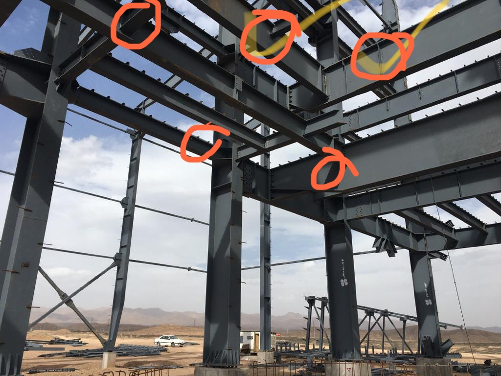
By making Certain Innovative Modifications in the structures (AS SHOWN IN THE MARKED AREAS BELOW) during erection. Next Part comes at the time of Floor Casting of the Furnace Floor.
I²R Losses are Minimized by using Properly Designed Secondary Circuit. Bus-Tubes constitute the major portion of the secondary Circuit in a SAF. Instead of Conventional Circular Bus Tubes it is strongly advised to use Square Bus Tubes as shown here.
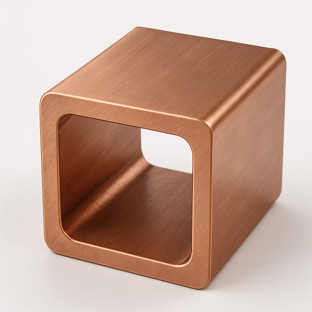
1. Optimum Cross Section Area of Copper
2. Optimum Vertical Spacing as well as Horizontal Spacing
3. Optimum Water Flow and Pressure consideration
4. 𝐋𝐨𝐫𝐞𝐧𝐭𝐳 𝐅𝐨𝐫𝐜𝐞 𝐁𝐞𝐭𝐰𝐞𝐞𝐧 𝐁𝐮𝐬 𝐓𝐮𝐛𝐞𝐬: When current flows through parallel bus tubes, a magnetic field is generated around each conductor. The interaction between this magnetic field and the current flowing in adjacent conductors results in a force, known as the 𝐋𝐨𝐫𝐞𝐧𝐭𝐳 𝐟𝐨𝐫𝐜𝐞. This force is repulsive as the currents flow in opposite directions.
5. The Lorentz force can cause mechanical stress, deformation to the bus tube system if not designed properly (Optimum Spacing) and proper pre calculations of the Lorentz Forces
Square tubes have a larger surface area. This increased surface area allows for more efficient 𝐌𝐚𝐠𝐧𝐞𝐭𝐢𝐜 𝐅𝐢𝐞𝐥𝐝 𝐍𝐞𝐮𝐭𝐫𝐚𝐥𝐢𝐳𝐚𝐭𝐢𝐨𝐧 and hence considerably 𝐌𝐢𝐧𝐢𝐦𝐢𝐳𝐢𝐧𝐠 𝐭𝐡𝐞 𝐈𝐦𝐩𝐞𝐝𝐞𝐧𝐝𝐚𝐜𝐞 𝐨𝐟 𝐬𝐞𝐜𝐨𝐧𝐝𝐚𝐫𝐲 𝐜𝐢𝐫𝐜𝐮𝐢𝐭 𝐞𝐯𝐞𝐧𝐭𝐮𝐚𝐥𝐥𝐲 𝐥𝐞𝐚𝐝𝐢𝐧𝐠 𝐭𝐨 𝐦𝐢𝐧𝐢𝐦𝐢𝐳𝐞 𝐈²𝐑 𝐋𝐨𝐬𝐬𝐞𝐬. 𝐈𝐦𝐩𝐫𝐨𝐯𝐞𝐝 𝐏𝐨𝐰𝐞𝐫 𝐅𝐚𝐜𝐭𝐨𝐫 𝐞𝐧𝐡𝐚𝐧𝐜𝐞𝐬 𝐏𝐫𝐨𝐝𝐮𝐜𝐭𝐢𝐯𝐢𝐭𝐲.
Furthermore, Magnetic Flux Linkage with surrounding structures is reduced considerably resulting in improved Power Factor and hence the productivity.
It is important to note here that for a 9-12 MVA Furnace, the quantity of Copper is saved up to 1.3 to 1.5 MT as compared to the conventional design.
For further minimizing the 𝐈²𝐑 Losses, it is strongly recommended to use Copper with Conductivity 103-105% IACS. (IACS stands for: INTERNATIONAL ANNEALED COPPER STANDARD). Zambian Copper with Silver Traces has conductivity of that order. This reduces losses further to 3-4%.
In order to make optimum use of the Transformer Capacity, the specially Secondary Compensation Capacitor Bank is installed (Tailor Made for Every Furnace). The beauty of this arrangement is that the Furnace Power Factor is maintained close to unity at all loads. As we increase the secondary voltage from Tap1 to the highest Tap, the KVAR output of the Capacitor Bank increases proportionately. Since the Furnace Power Factor is optimum, the efficiency and hence the production also increases.
For Example: If Power Factor of the Furnace is increased from 0.8 to 0.98, 10 MT production will increase per day for SiMn for a 9 MVA Furnace.
There are certain ways to use wasted heat for Pre-Heating ores before charging in the Furnace. However, it requires some Specially Designed Infrastructure, a one time investment.
From above explanation it can be easily assessed, how much the Cumulative Effect is.
In Addition to the above There are several other ways to Save Power.